
Charged Device Model (CDM) electrostatic discharge is a common cause of microelectronic circuit failure. Sensitive devices can be seriously damaged or destroyed by a CDM discharge at relatively low voltage. This often occurs when the static charged device contacts a metal surface at a different potential. Such an electrostatic discharge often has an extremely fast rise time.
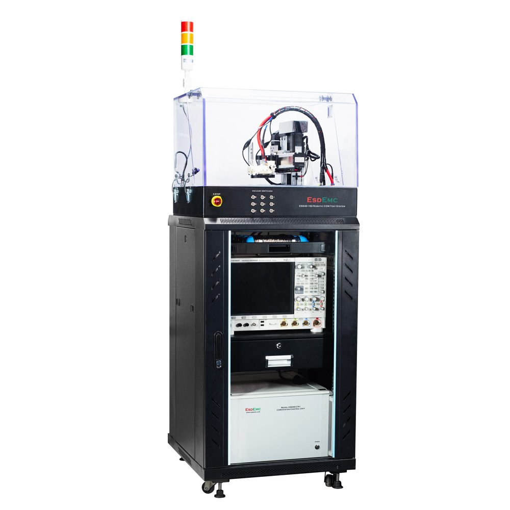
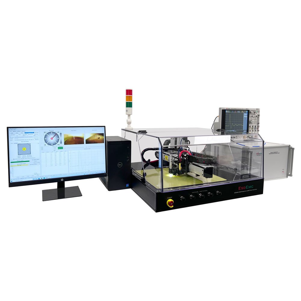
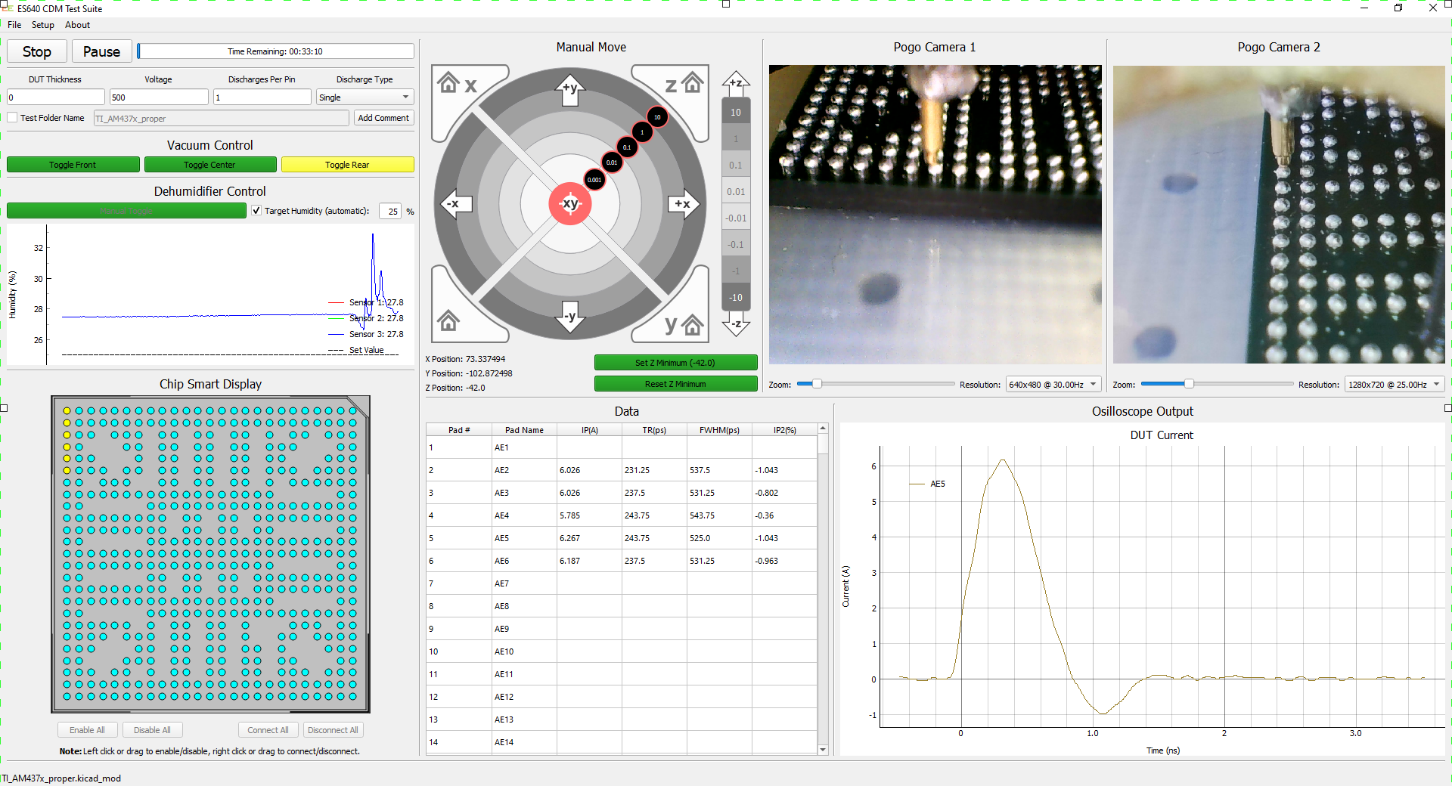
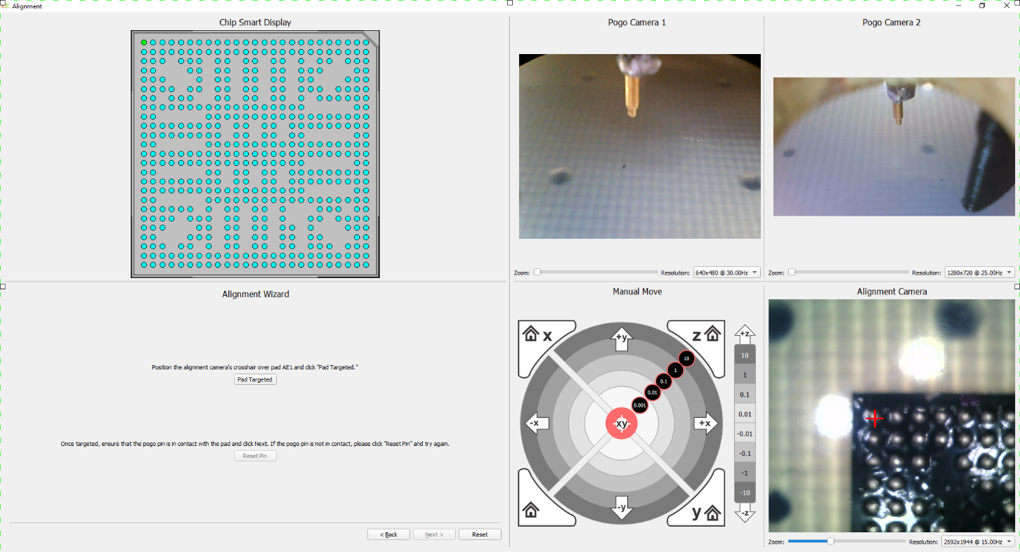
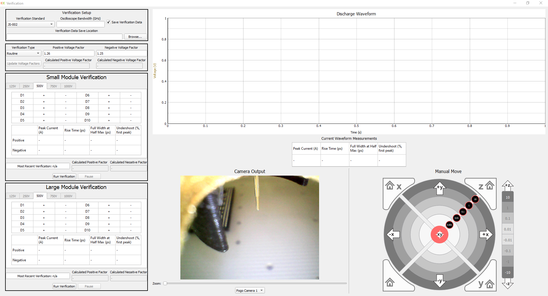
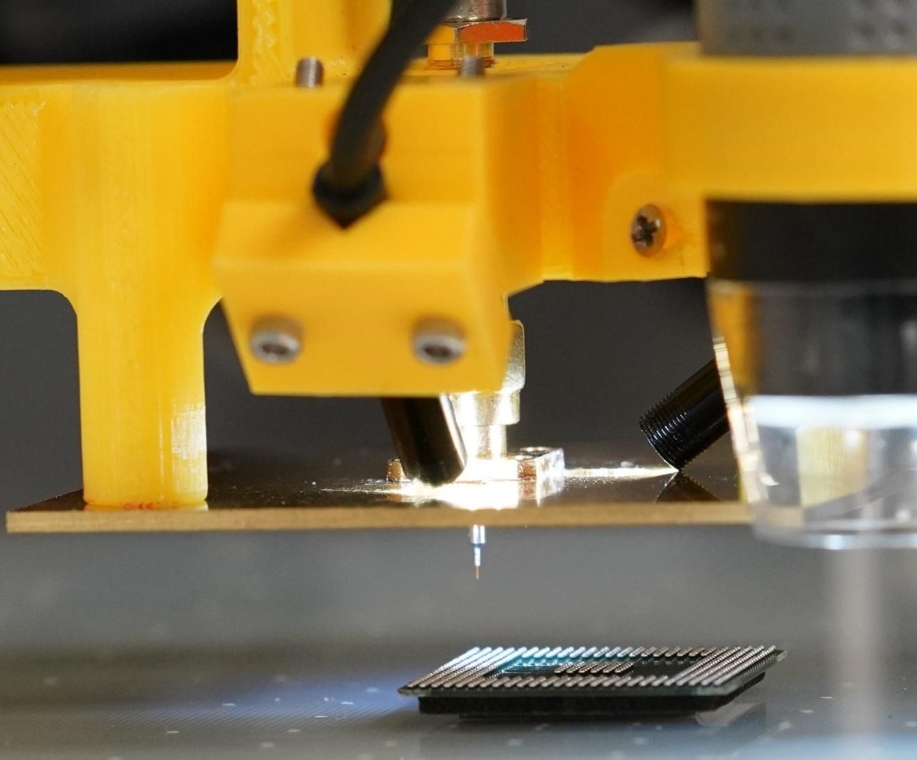
The Model ES640 is a robotic CDM (Charged Device Model) tester designed to meet all popular CDM ESD test methods, allowing both field induced air discharge methods (FICDM) and relay-based contact discharge methods (LI-CCDM, CC-TLP, RP-CCDM). The system includes a computer, environment-controlled chamber, precision XYZ motion system, different types of CDM tester modules, and an automated test and data analysis software.
Charged Device Model (CDM) electrostatic discharge is a common cause of microelectronic circuit failure. Sensitive devices can be seriously damaged or destroyed by a CDM discharge at relatively low voltage. This often occurs when the static charged device contacts a metal surface at a different potential. Such an electrostatic discharge often has an extremely fast rise time.
The Model ES640 is a robotic CDM (Charged Device Model) tester designed to meet all popular CDM ESD test methods, allowing both field induced air discharge methods (FICDM) and relay based contact discharge methods (LI-CCDM, CC-TLP, RP-CCDM). The system includes a computer, environment-controlled chamber, precision XYZ motion system, different types of CDM tester modules, and an automated test and data analysis software.
| Parameters | ES640-150 | ES640-150 + CP1 Option | ES640-300 | Units | Comments |
| Max XY Motion Area | ≥ 150 X 150 | ≥200 X 150 | ≥ 300 X 300 | mm | Probe motion area |
| Max DUT Area | 160 X 160 | 210 X 200 | 375 X 425 | mm | MAX Field plate area for DUT |
| Field Plate Area | 210 X 210 | 260 X 210 | 395 X 470 | mm | Field plate area |
| Max Z Travel Distance | ≥ 50 | mm | Customizable | ||
| Min X, Y, Z Step Size | 100 | nm | |||
| Reposition Repeatability | ≤ ±6 | μm | |||
| Voltage Range | ± 5 to ±2000 or ±4000 | V | Default 2000V, customizable | ||
| Min Voltage Step | 1 | V | |||
| Voltage Accuracy | ± 1% ±1V | % V | |||
| XY Vision Resolution | 1920 X 1080 | Pixel | Zoom & Pan | ||
| Vertical Vision Resolution | 2592 X 1944 | Pixel | Zoom & Pan | ||
| Operating Temperature | 10 to 40 | (°C) | |||
| Operating Humidity | 0 to 80 | % | |||
| Power Supply | 120-240 VAC, 50/60 Hz | VAC | |||
| Power Consumption | 300 | W | |||
| N2 or CDA Pressure | 10 – 120 | PSI | |||
| N2 or CDA Peak Usage | 0.2 cfm or 0.34 m3h | ||||
| 300 N2 Tank Avg Usage | ~ 19 | hour | Continuous @ 40RH environment | ||
| Desiccant Avg Usage | ~ 24 | hour | Continuous @ 40RH environment | ||
| Line | Part # or Option # | Description |
| ES640 Charged Device Model (CDM) Test System | ||
| 1.1 | ES640-150 | CDM platform, 150 X 150 mm Test Area, 2 kV |
| 1.2 | ES640-150-CP1 | Field Plate Upgrade from 150 X 150 to 150 X 200 mm (Larger Test Area) |
| 1.3 | ES640-300 | CDM platform, 300 X 300 mm Test Area, 2 kV |
| 1.4 | ES640-HC | Humidity Conditioning Unit (no Nitrogen needed), with desiccant tube *2 (Uses reusable desiccants, lower cost of usage than N2 or CDA) |
| 1.5 | ES640-CV4 | Charge Voltage Upgrade from 2kV to 4 kV |
| ANSI/ESDA/JEDEC JS-002 Standard Related Test Solution
(Followed standards include AEC_Q100-011D, AEC_Q101-005A) |
||
| 2.1 | ES640-JS002 | JS-002 Solution – System Integration Package
(Including One ES640-JS002-1 Test Fixture) |
| 2.2 | ES640-JS002-C | JS002/C101 Calibration Disc (6.8 pF and 55 pF) |
| 2.3 | ES640-JS002-1 | JS-002 Test Fixture #1 (Discharge Tip 250 µm, body diameter 350 µm) |
| 2.4 | ES640-JS002-2 | JS-002 Test Fixture #2 (Discharge Tip 120 µm, body diameter 200 µm) |
| 2.5 | ES640-JS002-6 | JS-002 Test Fixture #6 (Discharge Tip 5 µm, body diameter 200 µm), small sharp needle for wafer device |
| 2.6 | ES640-JS002-7 | JS-002 Test Fixture #7 (Discharge Tip 220 µm, body diameter 300 µm), allowing reaching 4kV TC (voltage factor <=1) |
| ANSI/ESD S5.3.1-2009 Standard Related Solution
(Not recommend for new designs) |
||
| 3.1 | ES640-S09-F | ANSI/ESD S5.3.1-2009_FI-CDM Discharge Unit |
| 3.2 | ES640-S09-D | ANSI/ESD S5.3.1-2009_D-CDM Discharge Unit |
| 3.3 | ES640-S09-C | ANSI/ESD FR4 Calibration Module (4 and 30 pF) |
| 3.4 | ES640-J13 | JEDEC-JESD22-C101F-2013 FI-CDM Discharge Unit |
| RP-CCDM Contact First CDM Solutions
(New methods for discharge stability improvements, not standardized yet) |
||
| 4.1 | ES640-RPCCDM | ESDEMC Patented Contact First CDM Solution
(Very repeatable contact first method, meets JS002 requirement, not require VF-TLP) (Including one ES640-PRCCDM-P1 Discharge Unit) |
| 4.2 | ES640-RPCCDM-P1 | RP-CCDM Discharge Unit for Packaged Device |
| 4.3 | ES640-RPCCDM-W1 | RP-CCDM Discharge Unit for Bare-die & Wafer Device |
| LI-CCDM Contact First CDM solution | ||
| 5.1 | ES640-LICCDM | LI-CCDM Discharge Solution – System Integration Package
(Including one ES640-LICCDM -P1 Discharge unit, require VF-TLP) |
| 5.2 | ES640-LICCDM-P1 | LI-CCDM Discharge Unit for Packaged Device |
| 5.3 | ES640-LICCDM-W1 | LI-CCDM Discharge Unit for Bare-die & Wafer Device |
| 5.4 | ES640-VFTLP | VF-TLP module for CC-TLP or LI-CCDM Method
(This VF-TLP module is a compact VF-TLP for the ES640 system. The default configuration is 1 rise-time + 1 pulse-width with limited expansion capability. If more pulse shape options are needed, model ES622 TLP/VF-TLP is the best option) |
| CC-TLP Solution | ||
| 6.1 | ES640-CCTLP | CC-TLP Solution – System Integration Package
(Including 1 set of ES640-CCTLP-1-50 & calibration gauge) |
| 6.2 | CC-TLP-1-50 | CC-TLP Discharge Unit with 50mm OD GND Plate |
| 6.3 | CC-TLP-1-100 | CC-TLP Discharge Unit with 100mm OD GND Plate |
| 6.4 | CC-TLP-1-Cal | CC-TLP calibration gauge for needle height |
| Test Fixture Options | ||
| 7.1 | ES640-TF1 | Standard CDM test fixture |
| 7.2 | ES640-TF2 | 1mm CDM test fixture |
| 7.3 | ES640-TFC | Customized CDM test fixture |
| Third Party Instruments for CDM System | ||
| 8.1 | MISC-OSC1G | Digital Oscilloscope (1 GHz bandwidth) |
| 8.2 | MISC-OSC6G | Digital Oscilloscope (6 GHz bandwidth) |